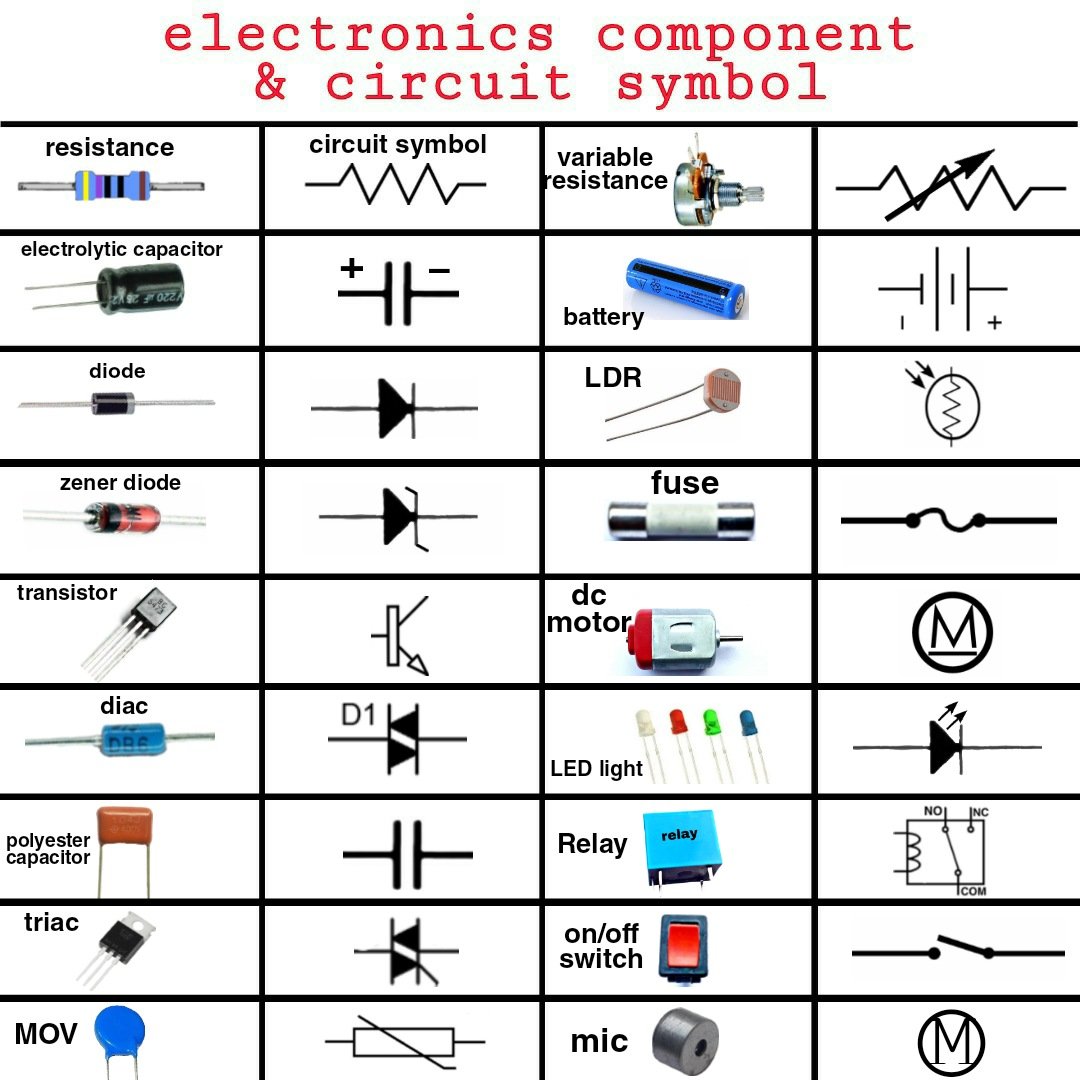
Ever felt lost staring at an electrical blueprint, as if it were written in a secret language? You're not alone. Just like sheet music guides a musician or architectural plans direct a builder, circuit diagram symbols & components form the universal language of electronics. They tell a story of current flow, voltage regulation, and component interaction, translating complex physical setups into clear, concise graphical representations. Mastering these symbols isn't just for seasoned engineers; it's a fundamental skill that unlocks a deeper understanding of the electronic world around us.
This guide is your Rosetta Stone to that world, designed to transform you from a bewildered observer into a confident interpreter of circuit schematics. We'll demystify each symbol, explain its function, and give you the practical knowledge to identify electronic parts on sight.
At a Glance: Your Quick Start Guide to Circuit Symbols
- Standardized Language: Electronic symbols follow international standards (IEEE Std 315, BS 3939) for universal understanding.
- Essential Building Blocks: Wires, power sources, resistors, capacitors, and diodes are your circuit's alphabet.
- Active vs. Passive: Understand the difference between components that control energy (like transistors) and those that consume or store it (like resistors and capacitors).
- Logic Gates: Learn the basic "decision-making" components of digital circuits.
- Meters & Sensors: Discover how to identify parts that measure and react to environmental changes.
- Switches & Outputs: Recognize how to turn circuits on/off and what devices produce light, sound, or motion.
- No Alterations: While you can design with them, the symbols themselves are fixed – you can't change how a resistor is drawn!
Why Learn the Language of Circuits? More Than Just Dots and Lines
Imagine trying to build a house without understanding blueprints, or cooking a meal without a recipe. Circuit diagrams are precisely that: the blueprints and recipes of electronics. Without a grasp of the fundamental circuit diagram symbols & components, you’re left guessing, risking errors, and missing out on the pure satisfaction of understanding how your devices tick.
These symbols aren't arbitrary squiggles; they are internationally standardized, primarily by the IEEE standard (IEEE Std 315) and the British Standard (BS 3939). This standardization ensures that a circuit diagram drawn in Tokyo can be understood by an engineer in New York, making collaboration and innovation truly global. While architectural drawings might allow for stylistic variations in power sources or lighting, the core electronic symbols remain fixed. Each component also often has a commonly used short name or abbreviation, which acts as a quick reference point on busy schematics.
The Building Blocks: Wire Connections
Let's start with the most basic element: how components connect. Wires are the highways of your circuit, guiding current from one point to another.
Wire Symbols
- Wire:
- What it is: A simple line representing a connection path.
- What it does: Conducts electrical current between two points.
- Wires Joined:
- What it is: Two or more wires meeting at a single point, marked by a "blob" or dot.
- What it does: Indicates that these wire segments are electrically connected, meaning current can flow freely between them.
- Unjoined Wires:
- What it is: Wires that cross each other without a "blob" or by "bridging" one over the other. Bridging (an arc over another line) is the more common and clearer practice to avoid confusion.
- What it does: Shows that wires are physically close or crossing in the diagram but are not electrically connected. Think of it like an overpass on a highway – traffic flows on different levels without mixing.
Powering Your Creations: Supply Symbols
Every circuit needs an energy source. These symbols represent how electricity enters your system.
Power Supply Symbols
- Cell:
- What it is: A single source of electrical energy.
- What it does: Provides a steady supply of voltage and current to the circuit.
- Battery (Abbr: ‘B’):
- What it is: Composed of two or more cells connected in series. Notice the different length terminals: the shorter one is negative (-), the longer one is positive (+).
- What it does: Provides a DC (Direct Current) power supply for a circuit, often at a higher voltage than a single cell.
- DC Supply:
- What it is: A generic symbol for a direct current power source. The line with the plus sign indicates the positive terminal.
- What it does: Delivers direct current, which flows consistently in one direction.
- AC Supply:
- What it is: A symbol indicating an alternating current power source, often represented by a sine wave inside a circle.
- What it does: Provides alternating current, where the direction of current flow periodically reverses. This is what comes out of your wall sockets.
- Fuse:
- What it is: A thin wire or metal strip encased in a protective housing.
- What it does: A safety device designed to break a circuit if excessive current flows, protecting more sensitive components from damage. It’s a one-time sacrificial component.
- Transformer (Abbr: ‘T’):
- What it is: Two coils (primary and secondary) shown side-by-side, linked by lines representing an iron core, but without a physical connection between the coils.
- What it does: Transfers AC electrical energy between circuits through mutual inductance, often changing voltage levels (stepping up or stepping down) without changing frequency.
- Earth/Ground:
- What it is: A symbol resembling an inverted triangle or a series of decreasing parallel lines.
- What it does: Represents the 0-volt reference point in electronic circuits, or the actual earth connection in radio and power circuits, providing a safety path for fault currents.
Controlling the Flow: Resistors
Resistors are the gatekeepers of your circuit, managing how much current can pass through.
Resistor Symbols
- Resistor (Abbr: ‘R’):
- What it is: A zig-zag line or a rectangular block.
- What it does: Restricts or "resists" the amount of electrical current flowing through a device, converting excess electrical energy into heat.
- Rheostat:
- What it is: A resistor symbol with an arrow pointing into it, indicating variability.
- What it does: A variable resistor used with two contacts to control current flow. Common applications include dimming lamps or adjusting the charging rate of a capacitor.
- Potentiometer (Abbr: ‘POT’):
- What it is: A resistor symbol with an arrow sweeping across it, showing three contacts.
- What it does: A variable resistor with three contacts, primarily used to control voltage flow. It can convert mechanical angle changes (like turning a knob) into electrical parameters, making it popular in volume controls.
- Preset:
- What it is: Similar to a potentiometer but with an arrow at an angle, often depicted as a small square or rectangle.
- What it does: A low-cost variable resistor, typically adjusted only once during circuit calibration using a screwdriver. Its resistance is set and generally left alone after the circuit design is finalized.
Storing Energy: Capacitors
Capacitors are like tiny temporary batteries, storing electrical energy and smoothing out signals.
Capacitor Symbols
- Capacitor (Abbr: ‘C’):
- What it is: Two parallel lines or plates, representing conductive plates separated by a dielectric.
- What it does: Stores electrical energy in an electric field. It acts as a filter, blocking DC signals while allowing AC signals to pass through.
- Capacitor – Polarized:
- What it is: Similar to a standard capacitor, but one plate is curved, or one terminal is marked with a plus sign.
- What it does: Has a specific polarity and must be connected correctly (positive to positive, negative to negative) to avoid damage. These are frequently found in power supply smoothing and timer circuits.
- Variable Capacitor:
- What it is: A capacitor symbol with an arrow crossing it at an angle.
- What it does: Allows its capacitance to be varied, usually by turning a knob. Trimmer capacitors are a smaller, more compact version used for fine-tuning circuits.
Directing Traffic: Diodes & Their Variants
Diodes are one-way valves for electricity, ensuring current flows in a specific direction.
Diode Symbols
- Diode (Abbr: ‘D’):
- What it is: A triangle pointing towards a line, with two terminals. The triangle is the anode (+), the line is the cathode (-).
- What it does: Permits electric current to flow in only one direction (from anode to cathode).
- Light Emitting Diode (LED):
- What it is: A standard diode symbol with two arrows pointing away from it, symbolizing emitted light.
- What it does: Emits light when electric current passes through it in the forward direction.
- Zener Diode (Abbr: ‘Z’):
- What it is: A diode symbol with a "Z" shape or bent line at the cathode.
- What it does: Allows current to flow in the reverse direction once a specific "Zener breakdown" voltage is reached, making it useful for voltage regulation.
- Photo Diode:
- What it is: A diode symbol with two arrows pointing towards it, symbolizing incoming light.
- What it does: Functions as a photo-detector, converting incident light into a corresponding electrical voltage or current.
- Tunnel Diode:
- What it is: A diode symbol with "wings" on the cathode line.
- What it does: Known for its extremely high-speed operation, leveraging quantum mechanical tunneling effects for unique characteristics like negative resistance.
- Schottky Diode:
- What it is: A diode symbol with "S" or "hook" shapes on the cathode line.
- What it does: Noted for its large forward voltage drop and fast switching speed, making it valuable in high-frequency switching power supplies and rectifier circuits.
Amplifying & Switching: Transistors
Transistors are the true workhorses of modern electronics, acting as electronic switches and amplifiers.
Transistor Symbols
- NPN Transistor (Abbr: ‘Q’):
- What it is: A circle containing a base line, a collector line, and an emitter line with an arrow pointing out from the base.
- What it does: A three-layer device (N-P-N) where a small current at the base controls a larger current flow between the collector and emitter. Used for amplification and switching.
- PNP Transistor (Abbr: ‘Q’):
- What it is: Similar to NPN, but the arrow on the emitter points in towards the base.
- What it does: A three-layer device (P-N-P) where a small current flowing out of the base controls a larger current flow between the collector and emitter. Also used for amplification and switching, but with opposite current directions compared to NPN.
- Phototransistor:
- What it is: An NPN or PNP transistor symbol with two arrows pointing towards the base, representing light input.
- What it does: Converts light into a corresponding electrical current. It's essentially a bipolar transistor where the base current is generated by light, and it can act like a photodiode if the emitter is left disconnected.
- Field Effect Transistor (FET):
- What it is: A general three-terminal transistor symbol with a gate, source, and drain.
- What it does: A transistor where an electric field (controlled by the gate voltage) regulates the conductivity of a channel, influencing the current flow between the source and drain. It relies on a single type of charge carrier (either electrons or holes).
- N-Channel Junction FET (JFET):
- What it is: A FET symbol where the gate connects to the channel with an arrow pointing in.
- What it does: The simplest type of FET, often used for switching applications and as a voltage-variable resistor. It features an N-type silicon bar with two P-type silicon pieces diffused into its middle, forming P-N junctions.
- P-Channel Junction FET (JFET):
- What it is: A FET symbol where the gate connects to the channel with an arrow pointing out.
- What it does: Similar to an N-channel JFET, but it uses a P-type semiconductor base sandwiched between two N-type junctions, with holes acting as the majority charge carriers.
- Metal Oxide Semiconductor FET (MOSFET) (Abbr: MOSFET):
- What it is: A FET symbol where the gate is insulated from the channel, often depicted with a broken line for the channel or a distinct gap.
- What it does: A three-terminal device where the gate bias controls the current flow. Known for low input capacitance and high input impedance, making them ideal for high-speed switching and amplification.
- Enhancement MOSFET (Abbr: e-MOSFET):
- What it is: A MOSFET symbol where the channel line is shown as a broken or dashed line, indicating it needs to be "enhanced."
- What it does: Lacks a physical channel during manufacturing. A voltage applied to the gate creates the channel, allowing current to flow between the drain and source.
- Depletion MOSFET (Abbr: d-MOSFET):
- What it is: A MOSFET symbol where the channel line is solid, indicating a pre-existing channel.
- What it does: Possesses a physically constructed channel, enabling current to flow between the drain and source even with zero gate voltage. The gate voltage can then deplete or reduce this channel's conductivity.
The Brains of the Circuit: Logic Gates
These are the fundamental decision-makers in digital electronics, performing basic logical operations.
Logic Gate Symbols
- AND Gate:
- What it is: A "D" shape with multiple inputs and a single output.
- What it does: Its output is HIGH (true) only if all its inputs are HIGH. Otherwise, the output is LOW (false).
- NAND Gate:
- What it is: An AND gate symbol followed by a small circle (inversion bubble) at the output.
- What it does: (NOT AND) The output is LOW only if all inputs are HIGH. In all other cases, the output is HIGH.
- OR Gate:
- What it is: A curved, shield-like shape with multiple inputs and a single output.
- What it does: Its output is HIGH if any of its inputs are HIGH. The output is LOW only if all inputs are LOW.
- NOR Gate:
- What it is: An OR gate symbol followed by a small circle (inversion bubble) at the output.
- What it does: (NOT OR) The output is LOW if any input is HIGH. The output is HIGH only if both inputs are LOW.
- EX-OR Gate:
- What it is: An OR gate symbol with an additional curved line at the input.
- What it does: (Exclusive OR) Its output is HIGH if the inputs are different (one HIGH, one LOW). The output is LOW if both inputs are the same (both LOW or both HIGH).
- EX-NOR Gate:
- What it is: An EX-OR gate symbol followed by a small circle (inversion bubble) at the output.
- What it does: (Exclusive NOT OR) Its output is HIGH if both inputs are the same. The output is LOW if the inputs are different.
- NOT Gate:
- What it is: A triangle followed by a small circle (inversion bubble) at the output. Has a single input.
- What it does: (Inverter) Simply inverts the input. If the input is HIGH, the output is LOW, and vice-versa.
Measuring & Sensing: Keeping an Eye on Your Circuit
These components allow you to monitor your circuit's behavior or enable it to react to its environment.
Meter Symbols
- Voltmeter:
- What it is: A circle with the letter "V" inside.
- What it does: Measures the electrical potential difference (voltage) between two points in a circuit. Always connected in parallel.
- Ammeter:
- What it is: A circle with the letter "A" inside.
- What it does: Measures the electric current passing through a specific point in a circuit. Always connected in series.
- Galvanometer:
- What it is: A circle with the letter "G" inside.
- What it does: Measures very small currents, typically in the range of microamperes to milliamperes.
- Ohmmeter:
- What it is: A circle with the Greek letter Omega (Ω) inside.
- What it does: Measures the electrical resistance of a circuit or component.
- Oscilloscope:
- What it is: Often represented by a stylized waveform on a screen.
- What it does: A sophisticated instrument that measures and visually displays the voltage, time period, and overall shape of electrical signals over time.
Sensor Symbols
- Light Dependent Resistor (LDR) (Abbr: LDR):
- What it is: A resistor symbol enclosed in a circle, with two arrows pointing towards it (representing light).
- What it does: Converts light intensity into a corresponding resistance. Its resistance decreases as the light intensity falling on it increases.
- Thermistor (Abbr: ‘TH’):
- What it is: A resistor symbol with a diagonal line and often a "T" or "theta" symbol.
- What it does: Senses heat content (temperature) and converts it into a corresponding electrical resistance. Typically, resistance changes inversely with temperature.
The Interaction Point: Switches & Relays
Switches allow you to manually or electrically control the flow of current.
Switch Symbols
- Push Switch:
- What it is: Two contacts that close when a button is pressed, often depicted as a gap with a plunger and spring.
- What it does: Passes current only when it is actively being pressed (momentary contact). Once released, it opens.
- Push to Break Switch:
- What it is: Two contacts that are normally closed, opening when a button is pressed.
- What it does: Is usually in the closed (ON) position and opens (OFF) only when it is pressed. Releasing it restores the connection.
- Single Pole Single Throw Switch (SPST):
- What it is: A simple "knife" or "lever" switch with two terminals.
- What it does: An ON/OFF switch that connects or disconnects a single electrical path. Current flows only when it's in the "ON" position.
- Single Pole Double Throw Switch (SPDT):
- What it is: A switch with three terminals: one common, and two selectable positions.
- What it does: A "2-way" switch that connects a single input to one of two possible outputs. It can have a central OFF position. Used to direct current flow into two different paths.
- Double Pole Single Throw Switch (DPST):
- What it is: Essentially two SPST switches ganged together, operating simultaneously.
- What it does: A dual ON-OFF switch that opens or closes two separate circuits at once. Commonly used to isolate both live and neutral connections in mains electrical lines for safety.
- Double Pole Double Throw Switch (DPDT):
- What it is: Two SPDT switches ganged together.
- What it does: A dual 2-way switch that controls two separate circuits and can route their connections to two different sets of terminals. Often used as a reversing switch for electric motors.
- Relay (Abbr: ‘RY’):
- What it is: A coil symbol (inductor) next to a set of switch contacts, indicating an electromagnetically operated switch.
- What it does: An electrical switch that uses an electromagnet to operate one or more sets of switching contacts. It allows a low-power circuit to control a high-power circuit. Typically has three stages: Normally Open (NO), Normally Closed (NC), and Common (COM).
Hear It, See It, Feel It: Audio, Radio, and Output Devices
These components are how your circuit communicates with the outside world, converting electrical signals into sensory experiences or mechanical action.
Audio and Radio Device Symbols
- Microphone (Abbr: ‘MIC’):
- What it is: A circle with a line inside, representing a diaphragm.
- What it does: Converts sound waves into electrical energy.
- Earphone:
- What it is: A circle with an arc inside, resembling a speaker.
- What it does: Converts electrical energy (audio signals) into sound waves directly into the ear.
- Loudspeaker:
- What it is: A larger circle with an arc, or a cone-like shape.
- What it does: Converts an amplified version of electrical energy into audible sound waves for a wider audience.
- Piezo-Transducer:
- What it is: Often represented by a rectangle with a zigzag line and two connections, or a circle with a "P" inside.
- What it does: Utilizes the piezoelectric effect to convert electrical energy into sound (or vice-versa), often producing high-pitched tones in buzzers or sensors.
- Amplifier:
- What it is: A triangle pointing towards the output.
- What it does: Increases the amplitude (strength) of an electrical signal. This symbol can represent a single amplifier component or an entire complex amplification circuit.
- Aerial (Abbr: ‘AE’):
- What it is: A vertical line with a triangle or multiple horizontal lines at the top.
- What it does: Transmits or receives radio frequency (RF) signals, crucial for wireless communication.
Output Devices
- Lighting Lamp:
- What it is: A circle with a cross inside.
- What it does: Provides light output, typically for illumination purposes.
- Indicator Lamp:
- What it is: A circle with an "X" or an arc and a dot inside, sometimes with an arrow representing light.
- What it does: Converts electrical energy into light to signal a status or warning (e.g., a power-on light, a car dashboard warning).
- Heater:
- What it is: A squiggly line or coil shape.
- What it does: Converts electrical energy primarily into heat.
- Inductor (Abbr: ‘L’):
- What it is: A coil or spiral shape.
- What it does: Produces a magnetic field when current passes through its coil of wire, often around a soft iron core. It resists changes in current and is used in motors, filters, and tank circuits.
- Motor (Abbr: ‘M’):
- What it is: A circle with the letter "M" inside.
- What it does: Converts electrical energy into mechanical energy (rotary motion). It can also function in reverse as a generator.
- Bell:
- What it is: A bell-shaped outline.
- What it does: Produces sound as an output based on electrical energy input, often for signaling.
- Buzzer:
- What it is: A curved bracket shape with lines, or a simplified sound emitter.
- What it does: Produces a buzzing or beeping sound corresponding to electrical energy input, typically for alerts.
Putting It All Together: From Symbols to Schematics
Now that you've got a comprehensive grasp of individual circuit diagram symbols & components, you're ready to interpret the language of electronics. Remember, a schematic is more than just a collection of symbols; it's a narrative of how electrical energy travels and transforms within a system. Each line, dot, and shape contributes to the story of functionality.
When you encounter a complex diagram, break it down:
- Identify the Power Source: Where does the energy come from (battery, AC supply, etc.)?
- Trace the Path: Follow the wires to understand the flow of current.
- Recognize Components: What role does each resistor, capacitor, or transistor play? Are they controlling flow, storing energy, or amplifying signals?
- Understand Logic: If digital, how do the logic gates process information?
- Look for Outputs: What is the circuit doing? Is it lighting an LED, making a sound, or driving a motor?
With practice, interpreting circuit diagrams will become second nature. You’ll begin to see the elegance and efficiency in how designers arrange these fundamental building blocks to achieve incredible results, from the simplest LED circuit to the most intricate microprocessor. For an even deeper dive into the world of circuit diagrams, including best practices for reading and drawing them, we invite you to explore our circuit diagram guide.
Frequently Asked Questions About Circuit Symbols
Why are electronic symbols standardized?
Standardization (by bodies like IEEE and BS) ensures that circuit diagrams are universally understood, regardless of where they were drawn or by whom. This global consistency is crucial for collaboration, education, and avoiding costly misinterpretations in design and manufacturing.
Can I create my own symbols for special components?
While you can add notes or specific labels for unique components, the fundamental electronic symbols themselves are fixed by international standards. Altering them would break the universal language of circuit diagrams and lead to confusion. If you have a custom component, you'd typically represent it with a standard generic symbol (e.g., a rectangle) and then add detailed annotations or a separate datasheet reference.
What's the difference between a rheostat and a potentiometer?
Both are variable resistors, but they're used differently. A rheostat typically uses two terminals to vary the current flowing through a load. A potentiometer uses three terminals to vary the voltage across a load, acting as a voltage divider. Think of a rheostat as a dimmer switch for a single light, and a potentiometer as a volume knob controlling how much signal goes to an amplifier.
Why do some symbols have arrows pointing in or out (like LEDs or photodiodes)?
Arrows on a symbol often indicate interaction with energy that is not electrical.
- Arrows pointing out (e.g., LED): The component emits something (like light).
- Arrows pointing in (e.g., Photodiode, LDR, Phototransistor): The component receives something (like light or heat) and reacts to it.
What's the significance of the "blob" or dot on wire connections?
The "blob" or dot is critical! It unequivocally signifies an electrical connection between wires. If there's no blob where wires cross, they are not connected. This distinction is vital for circuit functionality and preventing short circuits. Using a "bridge" symbol for unjoined wires that cross is often preferred for ultimate clarity.